Computer Science
Data Representation
Program Design
Hardware & Software
Networks
Databases
Data Structures
Algorithms
Other
![]()


Computer Science
Computer Architecture
Three-Box Model
The three-box model is the simplest way to represent the internal components of a computer system.
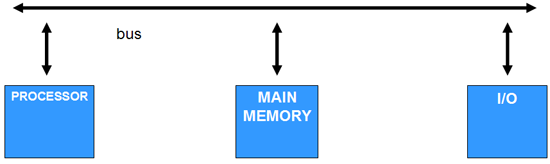
Processor
The main job of the processor is to execute programs and supervise and control the functioning of the other components.
Main Memory
Main memory is the location where instructions and data are stored. Memory is principally made up of RAM chips but may include one or more ROM chips.
Random Access Memory
Random access memory is readable and writable. RAM is volatile, its contents are wiped every time that the computer is switched off.
Read-Only Memory
ROM chips provide fast-access to non-volatile information. It tends to be used to store the instructions required to load the computer system.
Buses
A bus is a set of parallel wires that connect components of the computer system together. The bus that connects the boxes in the above diagram is known as the System or External Bus. In reality, this tends to be divided into three buses which carry different types of information.
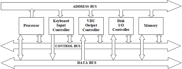
Data Bus
A bi-directional bus transporting data between components, typically consisting of 32 parallel wires.
Address Bus
A uni-directional bus, typically consisting of 32 wires, used to address memory and IO locations.
Control Bus
A bi-directional bus, typically consisting of 8 wires. It is used to transport control signals between the components.
Typical control lines include,
- Memory Write - causes data on the data bus to be written into the addressed location.
- Memory Read - causes data from the addressed location to be placed on the data bus.
- I/O Write - causes data on the data bus to be output to the addressed I/O port.
- I/O Read - causes data from the addressed I/O port to be placed on the data bus.
- Transfer ACK - indicates that data have been accepted from or placed on the data bus.
- Bus Request - indicates that component needs to gain control of bus.
- Bus Grant - indicates that a requesting component has been granted control of the system bus
- Interrupt request - indicates that an interrupt is pending.
- Interrupt ACK - acknowledges that the pending interrupt has been recognised.
- Clock - used to synchronise operations.
- Reset - initialises all components.
Expanding The Three-Box Model
In examinations, you may be presented with an expanded version of the above diagram. You are likely to have to identify some of the components.
You may see something like this,
Suppose that you are presented with the following diagram and asked to match up the names of components to the numbers on the diagram. The names of the components that you need to match are, processor, ROM, RAM, address bus, data bus and clock.
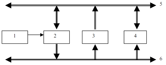
Clock: The role of the clock is to send timing signals. It is connected directly to the processor and not along any of the three buses. Item number 1 is the only box not connected to a bus and must therefore be the clock.
Processor: The processor is connected directly to the clock and must therefore be box number 2.
Address Bus: Wire number 6 must be the address bus. The processor is the only component that can place addresses on the bus.
Data Bus: Wire number 5 must therefore be the data bus.
ROM Common sense tells us that, since ROM is read-only, it must be the box that does not accept data from the data bus - box 3.
RAM Similarly, RAM must be the box that has a bi-directional connection to the data bus.